-- With member under same supervisor
Wednesday 14 November 2012
UPDATED FOR FLOW CHART AND BLOCK DIAGRAM
-- New flow Chat and block diagram
flow chart
flow chart
Block Diagram
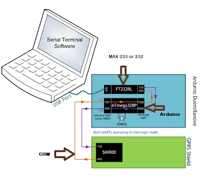
From this block diagram, we can look the operation
of flood monitoring system, in this project, we use battery as a main supply to
all component to operate. Sensor 1, sensor 2 and sensor 3 are water level
sensor to give the signal arduino atmega 328P and atmega 328P that have been
program send the data to GSM. GSM send the data to the number in the program.
SYSTEM PROTOTYPE
-- This system will install near the river or the place are high risk to flood, below the example this system will place:
Experiment Setup
overall view
circuit view
Result
message for level 1 ( First warning)
message for level 2 ( Second warning)
message for level 3 ( Last or third warning)
Sending at serial monitor
- the progress also can see at serial monitor in arduino software
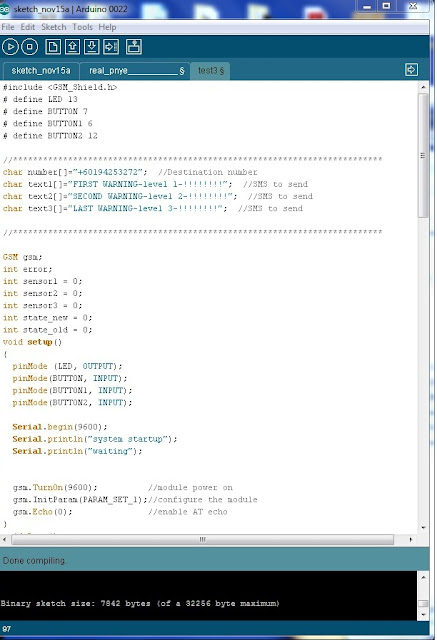
SYSTEM PROGRAMMING FOR FLOOD MONITORING SYSTEM USING GSM
#include <GSM_Shield.h>
# define LED 13
# define BUTTON 7
# define BUTTON1 6
# define BUTTON2 12
//**************************************************************************
char number[]="+60194253272"; //Destination number
char text1[]="FIRST WARNING-level 1-!!!!!!!!"; //SMS to send
char text2[]="SECOND WARNING-level 2-!!!!!!!!"; //SMS to send
char text3[]="LAST WARNING-level 3-!!!!!!!!"; //SMS to send
//**************************************************************************
GSM gsm;
int error;
int sensor1 = 0;
int sensor2 = 0;
int sensor3 = 0;
int state_new = 0;
int state_old = 0;
void setup()
{
pinMode (LED, OUTPUT);
pinMode(BUTTON, INPUT);
pinMode(BUTTON1, INPUT);
pinMode(BUTTON2, INPUT);
Serial.begin(9600);
Serial.println("system startup");
Serial.println("waiting");
gsm.TurnOn(9600); //module power on
gsm.InitParam(PARAM_SET_1);//configure the module
gsm.Echo(0); //enable AT echo
}
void loop()
{
Serial.println("ready to sent sms");
status_update:
if (state_new - state_old == 0)// no update in sensor status
{
goto update_sensor;
}
else if (state_new - state_old < 0 || state_new - state_old > 0) // changes in status
{
goto texting;
}
status_update1:
if (state_new - state_old == 0)// no update in sensor status
{
goto update_sensor;
}
else if (state_new - state_old < 0 || state_new - state_old > 0) // changes in status
{
goto texting2;
}
status_update2:
if (state_new - state_old == 0)// no update in sensor status
{
goto update_sensor;
}
else if (state_new - state_old < 0 || state_new - state_old > 0) // changes in status
{
goto texting3;
}
update_sensor:
sensor1 = digitalRead (BUTTON); //sensor1
sensor2 = digitalRead (BUTTON1); //sensor2
sensor3 = digitalRead (BUTTON2); //sensor3
if (sensor1 == LOW)
{
if (sensor2 == LOW)
{
if (sensor3 == LOW)
{
text3;
state_new = 3;
goto status_update2;
}
text2;
state_new = 2;
goto status_update1;
}
text1;
state_new = 1;
goto status_update;
}
else
{
state_new = 0;
}
goto update_sensor;
texting:
digitalWrite(LED, HIGH);
Serial.print("Send SMS to ");
Serial.println(number);
error=gsm.SendSMS(number,text1);
Serial.println("SMS sent \n");
state_old = state_new;
goto update_sensor;
texting2:
digitalWrite(LED, HIGH);
Serial.print("Send SMS to ");
Serial.println(number);
error=gsm.SendSMS(number,text2);
Serial.println("SMS sent \n");
state_old = state_new;
goto update_sensor;
texting3:
digitalWrite(LED, HIGH);
Serial.print("Send SMS to ");
Serial.println(number);
error=gsm.SendSMS(number,text3);
Serial.println("SMS sent \n");
state_old = state_new;
goto update_sensor;
}
-- below the program in arduino software
}
TABLE FOR PROGRAM
- Get helping from advisor to do this table.
function of table:
function of table:
- easy to do the program
- to know sensor work sequence
- to avoid waste on time to do the program
SENSOR
- Float Switch
Features:
- Miniature general purpose plastic float switch*
- Normally-closed; reversible to normally open**
- Float magnet is encased inside the float
- 48" leads (22 gauge wire) offer project flexibility
- M8 fitting – includes a nut and sealing o-ring
- Great for:
- general water level control applications
- aquarium top-off applications
- humidification/de-humidification applications
- hydroponics projects
- water features
- air conditioning drain pan applications
- Don’t use in heavy duty applications like sewage pumps
SIM 900 GSM/GPRS SHIELD FOR ARDUINO
IComsat is a GSM/GPRS shield for Arduino and based on the SIM900 Quad-band GSM/GPRS module. It is controlled via AT commands and fully compatible with Arduino.
TOP
BOTTOM
Features
- Quad-Band 850/ 900/ 1800/ 1900 MHz
- GPRS multi-slot class 10/8
- GPRS mobile station class B
- Compliant to GSM phase 2/2+
- Class 4 (2 W @850/ 900 MHz)
- Class 1 (1 W @ 1800/1900MHz)
- Control via AT commands (GSM 07.07 ,07.05 and SIMCOM enhanced AT Commands)
- Low power consumption: 1.5mA(sleep mode)
- Operation temperature: -40°C to +85 °C
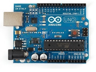
example Arduino Uno R3
- for easy to test the sensor, I use arduino uno R3
what is arduino?
Arduino can sense the environment by receiving input from a variety of sensors and can affect its surroundings by controlling lights, motors, and other actuators. The microcontroller on the board is programmed using the Arduino programming language (based on Wiring) and the Arduino development environment (based on Processing). Arduino projects can be stand-alone or they can communicate with software running on a computer (e.g. Flash, Processing, MaxMSP)
PCB DESIGN
- Procedure for PCB Design
STEP 1( Convert into PDF)
STEP 2( Print at sticker paper )
STEP 3 ( Iron at PCB Board)
STEP 5 ( Draw line back to ensure the line are not erased)
STEP 1( Convert into PDF)
STEP 2( Print at sticker paper )
STEP 3 ( Iron at PCB Board)

STEP 4 ( After finish iron )
|
STEP 6 ( Etching the board)
STEP 7 ( clean the board with abrasive paper)
STEP 8 ( Test the short line)
STEP 9 ( Drill)
STEP 10 ( Solder component on PCB Board)
STEP 11 ( Finish)
LIST OF COMPONENT USED IN ARDUINO SCHEMATIC
| List of Components: -10 Ways Straight Box Header | |||||||||||||||||||
| -2510 PCB Connector 4 Ways | |||||||||||||||||||
| -6x6x1 Push Button 4Pin | |||||||||||||||||||
| -9V Battery Holder | |||||||||||||||||||
|
TECHNICAL REPORT
Technical Report 1
Title:
A Socia Economic Monitoring and Evaluation System for the Rufiji
Enviromrnt Management Project.
Author:
Emmanuel R. Mbiha
Project Manager,
Rufiji Environment
Management Project
Ephraim M. M. Senkondo
Ass.Project Manager,
Rufiji Environment
Management Project
Link:
Summary:
Monitoring
and Evaluation (M&E) is a valuable tool for better planning and
implementation of projects and programs. However a tool is only as good as its
user. The Rufiji Environment Management Project (REMP) proposal indicated the
importance of M&E as a component in the project although an M&E system
was not incorporated right at the beginning. The project envisaged the design
of an M&E system after completion of part one of the first phase of the
project. This study was therefore commissioned to fulfill part of the tasks
involved in designing an M&E system needed to strengthen project
implementation. In this study major emphasis was placed on socio-economic
aspects of the project.
Technical Report 2
Title:
Flood
Forecasting and Early Warning System (FFEWS) an Alternative Technology for
Flood Management System and Damage Reduction.
Author:
Semu Ayalew Moges
Arba
Minch University,
School
of Graduate Studies
Link:
www.ec.europa.eu/energy/.../doc/
Summary:
This concept note was developed as a response to the recent
flooding in Ethiopia which ravaged almost the entire country. From emerging
reports of various climate centers, the rainfall pattern is likely to show
increasing trends in the eastern part of Africa, while it may exhibit
decreasing trend in the western and southern part of Africa. The evidence of
recent flooding coupled with the climate prediction centers makes Ethiopia more
vulnerable that ever. Therefore, it is high time for Ethiopia to work towards
developing adaptation and flood management mechanism to cope with the future
flood situations. This concept note deals with one form of flood management
system which is based on flood forecasting and warning system. The proposal emphasis
the need for Flood Forecasting and Early Warning System (FFEWS) in Ethiopia and
suggests possible Institutional framework and real time communication strategy
with involved institutions. It also highlights the need for research and
development support in the process of developing the FFEWS. Finally the
training needs and capacity building aspect have been considered an element of
successful Flood FFEWS Centre.
Technical Report 3
Title:
An
economic analysis of flood warning
Author:
Paula Holland
Senior Adviser Natural Resources
Governance
SOPAC
Secretariat
Link:
ict.sopac.org/VirLib/ER0122.pdf
Summary:
Navua town and
its surrounding area are subject to flooding approximately once every seven years.
The most recent serious floods occurred in 2004 and imposed considerable
financial and physical damage. Under the European Development Fund (EDF)
project Reducing Vulnerability in Pacific ACP States, SOPAC
worked with the Government of Fiji to establish a flood warning system for the
town of Navua and nearby communities. The system will involve close monitoring of
rainfall and river levels with the expectation that flood warnings can
initially be issued up to three hours before a flood and subsequently up to six
hours once the system has been operating for some time. Once established, the
warning system will require on-going financial support to maintain its
operation.
PROJECT PROPOSAL (DRAFT 2)
FLOOD MONITORING SYSTEM USING GSM
STUDENT NAME: MUHAMMAD YUSOF BIN MAMAT
ID NO: 51210210286
INSTITUTION: BRITISH MALAYSIAN INSTITUTE
SECTION: ELECTRICAL
SUPERVISOR: SIR MUHYI BIN YAAKOP
1. Introduction
Today aims of new technologies are increase and make a work easier. Technical field’s work also is that uses the new technologies because of the technologies are growth like a mushroom after raining. Project flood monitoring system using GSM is the one of new project to introduce to technical field that use GSM system module, GSM modem is specialized type of modem that operates over subscription based wireless networks which is similar to a mobile phone. A GSM modem accepts a SIM card, and basically acts like a mobile phone for the computer. Traditional modem is attached to computers for ‘dial-up’ to connect with other computer systems. A GSM modem operates in a similar fashion, except that it sends and receives data through radio waves rather than a telephone line. in this system we use the GSM send notification to the cell phone person that in charge in this case went its detect the signal from the sensor. With this project we detected increased levels of water in an area and provide early warning to residents about any of flooding, with this we can reduce the cost of flood losses in the event of damage to property.
In this project also we combine SCADA system to make easier the person in chargeto see and monitoring the system. The SCADA systems are used to monitor and control a plant or equipment in industries such as telecommunications, water and waste control, energy, oil and gas refining and transportation. A SCADA system gathers information, such as where a leak on a pipeline has occurred, transfers the information back to a central site, alerting the home station that the leak has occurred, carrying out necessary analysis and control, such as determining if the leak is critical, and displaying the information in a logical and organized fashion. SCADA systems can be relatively simple, such as one that monitors environmental conditions of a small office building, or incredibly complex, such as a system that monitors all the activity in a nuclear power plant or the activity of a municipal water system.
2. Statement Problem
2.1 First case:
Terengganu: A total of 47 flood victims involving 11 families that had been evacuated to a relief centre in Kampung Tasek in Setiu, Terengganu, are still there. A total of 47 flood victims involving 11 families that had been evacuated to a relief centre in Kampung Tasek in Setiu, Terengganu, are still there.
He said precautionary measures were being taken with the Fire and Rescue Department on stand by for any emergency situation. The Drainage and Irrigation Department Malaysia (JPS) has listed high water levels for rivers in Setiu, Marang, Hulu Terengganu, Besut in Terengganu as well as in Sik in Kedah.So far, 450 people in Johor, 48 people in Malacca and 47 people in Terengganu have been affected by the floods.
2.2 Second case:
Kuching: The flood may have receded in most areas but the affected families are now counting their losses. And a family from Kampung Karu, about 38 kilometres along Jalan Puncak Borneo, among those affected by the flood, estimated their loss to be almost RM10,000.
Among the damaged properties, the family claimed, were eight cabinets, a laptop, a motorcar and a motorcycle which were submerged by the flood waters, which rose nearly one metre high within five minutes. The incident happened about 1am on Dec 26 during a heavy downpour
In this case they don’t know went the flood will happen, with this system, the sensor will detect the increase of water at river and give the signal to micro controller and micro controller send the data to GSM and GSM send the notification to the person in charge. After that we can tell to villages about the flood will happen. Therefore people can save their property before the flood
3. Objectives:
· To monitoring flood system with SCADA.
· To ensure GSM can work to send the data to the phone.
·
4. Technical Approach:
From this block diagram, we can look the operation of flood monitoring system, in this project, we use battery as a main supply to all component to operate. Sensor 1and sensor 2 are water level sensor to give the signal to microcontroller PIC and PIC that have been program send the data to GSM. SCADA is a monitoring system to see the operation or flow of project. The valve is to control water flow to the tank.
4.2 Overview Device
4.2.1 GSM modem
GSM modem is specialized type of modem that operates over subscription based wireless networks which is similar to a mobile phone. A GSM modem accepts a SIM card, and basically acts like a mobile phone for the computer. Traditional modem is attached to computers for ‘dial-up’ to connect with other computer systems. A GSM modem operates in a similar fashion, except that it sends and receives data through radio waves rather than a telephone line.
- Besides the dial-up connection, GSM modem can also be used for sending and receiving SMS which is also one of the key features of GSM Modem are as follow:
- · RS-232 Interface
- · Tri-Band: GSM900, GSM1800 and GSM1900
- · Support TCP/IP
- · Support standard extended open AT commands
- · Support GPRS class 10
- · Accept supply voltage from 5 to 12V
- · Support PDU and Text mode for SMS
4.2.2 PIC 16F877A
There are three memory blocks in each of the PIC16F877A MCUs. The Program Memory and Data Memory have separate buses so that concurrent access can occur and is detailed in this section.
The PIC16F87X devices have a 13-bit program counter capable of addressing an 8K x 14 program memory space. The PIC16F877/876 devices have 8K x 14 words of FLASH program memory, and the PIC16F873/874 devices have 4K x 14. Accessing a location above the physically implemented address will cause a wraparound. The RESET vector is at 0000h and the interrupt vector is at 0004h.
Characteristic
|
PIC16F87X
|
Pins
|
28/40
|
Timers
|
3
|
Interrupts
|
13 or 14
|
Communication
|
PSP, USART,
SSP (SPI, I2C
Master/Slave)
|
Communication
|
20 MHz
|
Voltage
|
2.0V - 5.5V
|
A/D
|
10-bit
|
CCP
|
2
|
Program
Memory
|
4K, 8K
FLASH
|
RAM
|
192, 368
bytes
|
EEPROM data
|
128, 256
bytes
|
Other
|
In-Circuit
Debugger,
Low Voltage
Programming
|
4.2.3 MAX 232
The MAX232 contains four sections they are dual charge-pump DC-DC voltage converters, RS 232 drivers, RS-232 receivers, and receiver and transmitter enable control inputs. The MAX232 has two internal charge-pumps that convert +5V to ±10V (unloaded) for RS-232 driver operation. The first converter uses capacitor C1 to double the +5V input to +10V on C3 at the V+ output. The second converter uses capacitor C2 to invert +10V to -10V on C4 at the V- output.
4.2.4 Float Switch (RSF50 Series)
The RSF50 series are compact vertically mounted devices with a single switch point. Mounting is in the top or bottom of the tank from the inside, so access to the inside of the tank is required. Typical applications include printing systems and chemical dosing equipment. They are manufactured in a variety of materials, with a choice of gasket materials to suit most commonly used liquids. The switch action may be reversed by removing the float, inverting it, and then refitting it to the stem.
RSF50 Series Information:
- Vertical Float
- 25 VA Switching Power
- 0.6 Amp Switching Current
- NO/NC Contacts
- Compact Design
- Switching Power (VA): 25 Volt-Amps
- Switching Voltage AC: 240 Volts AC
- Switching Voltage DC: 120 Volts DC
5. PROJECT MANAGEMENT
5.1 Budget
Table shown are expected cost and expenses in order to complete the final project.
No
|
Components, Circuits & Equipments
|
Estimated Price (RM)
|
1
|
GSM modem
|
480.00
|
2
|
Pic Circuit
|
60.00
|
3
|
Component used
|
40.00
|
4
|
Water pump
|
30.00
|
TOTAL COST
|
610.00
|
*The price is subject to change.
5.2 Gant Chart
Project title: Flood monitoring system using GSM
Below we can see the estimate time to do the project, the project will start on 16 January 2012 and end at 13 September 2012. We take 1 year to complete this project.
6. Conclusion
In conclusion, we hope this project can successful be accept and complete as soon as possible and follow the schedule. By the research that has been done it is good enough for improvement all part this project. Flood monitoring system will be produce because to solve the current situation using GSM module to send the notification before flood happens. In this project also we have monitor the system automatically method if we use manually method wee need to check every time at that place. To improve this monitoring system we use SCADA to see and monitor the system running. SCADA has been create to help we monitor every where in Malaysia. Flood monitoring system can be commercial because it can help government to reduce losses went flood happen.
7. References
Subscribe to:
Posts (Atom)


